For a long time, radios led the list of the most significant inventions of mankind. The first such devices are now reconstructed and changed to a modern way, however, little has changed in the assembly scheme - the same antenna, the same grounding and an oscillating circuit to filter out an unnecessary signal. Undoubtedly, the circuitry has become much more complicated since the time of the creator of the radio, Popov. Its followers developed transistors and microcircuits to reproduce a better and more energy-consuming signal.
Why is it better to start with simple schemes?
If you understand a simple radio circuit, then you can be sure that most of the path to success in the field of assembly and operation has already been mastered. In this article we will analyze several schemes of such devices, the history of their occurrence and the main characteristics: frequency, range, etc.
History reference
May 7, 1895 is considered the birthday of the radio. On this day, the Russian scientist A. S. Popov demonstrated his apparatus at a meeting of the Russian Physicochemical Society.
In 1899, the first 45 km long radio link was built between the island of Hogland and the city of Kotka. During the First World War, a direct-amplification receiver and electron tubes became widespread. During the war, the availability of radio was strategically necessary.
In 1918, both in France, Germany and the USA, the scientists L. Levvy, L. Schottky and E. Armstrong developed the method of superheterodyne reception, but due to weak electron tubes this principle was widely used only in the 1930s.
Transistor devices appeared and developed in the 50s and 60s. The first widely used radio receiver with four Regency TR-1 transistors was created by German physicist Herbert Mathare with the support of industrialist Jacob Michael. It went on sale in the United States in 1954. All old radios worked on transistors.
In the 70s, the study and implementation of integrated circuits began. Now receivers are developing with the help of large integration of nodes and digital signal processing.
Instrument Specifications
Both old and modern radios have certain characteristics:
- Sensitivity is the ability to receive weak signals.
- Dynamic range - measured in Hertz.
- Immunity
- Selectivity (selectivity) - the ability to suppress extraneous signals.
- Level of own noise.
- Stability.
These characteristics do not change in new generations of receivers and determine their performance and ease of use.
The principle of operation of radios
In the most general form, the USSR radios worked according to the following scheme:
- Due to fluctuations in the electromagnetic field, an alternating current appears in the antenna.
- Oscillations are filtered (selectivity) to separate information from interference, i.e., its important component is extracted from the signal.
- The received signal is converted to sound (in the case of radios).
According to a similar principle, an image appears on a TV, digital data is transmitted, radio-controlled equipment (children's helicopters, cars) works.
The first receiver looked more like a glass tube with two electrodes and sawdust inside. The work was carried out according to the principle of the action of charges on a metal powder. The receiver had a huge resistance by today's standards (up to 1000 Ohms) due to the fact that the sawdust had poor contact with each other, and part of the charge slipped into the airspace where it was scattered. Over time, these filings were replaced by an oscillating circuit and transistors to conserve and transfer energy.
Depending on the individual receiver circuitry, the signal in it can undergo additional filtering by amplitude and frequency, amplification, digitization for further software processing, etc. A simple radio receiver circuit provides for a single signal processing.
Terminology
An oscillating circuit in its simplest form is a coil and a capacitor, closed in a circuit. With the help of them, from all the incoming signals, it is possible to select the desired due to the natural frequency of the oscillation circuit. USSR radios, as well as modern devices, are based on this segment. How does it all work?
As a rule, radio receivers are powered by batteries, the number of which varies from 1 to 9. For transistor devices, 7D-0.1 batteries and Kron type batteries with voltage up to 9 V are widely used. The more batteries a simple radio circuit requires, the longer it will work .
According to the frequency of received signals, the devices are divided into the following types:
- Longwave (LW) - from 150 to 450 kHz (easily scattered in the ionosphere). Ground waves are of importance, the intensity of which decreases with distance.
- Medium-wave (SW) - from 500 to 1500 kHz (easily scattered in the ionosphere during the day, but reflected at night). In daylight, the radius of action is determined by mundane waves, at night - reflected.
- Shortwave (HF) - from 3 to 30 MHz (they do not land, they are exclusively reflected by the ionosphere, therefore there is a radio silence zone around the receiver). With low transmitter power, short waves can propagate over long distances.
- Ultrashort-wave (VHF) - from 30 to 300 MHz (have a high contacting ability, as a rule, are reflected by the ionosphere and easily go around obstacles).
- High-frequency (HF) - from 300 MHz to 3 GHz (used in cellular communications and Wi-Fi, operate within sight, do not go around obstacles and spread linearly).
- Ultra High Frequency (EHF) - from 3 to 30 GHz (used for satellite communications, reflected from obstacles and operate within line of sight).
- Hyper-high-frequency (GHF) - from 30 GHz to 300 GHz (do not go around obstacles and are reflected like light, they are used extremely limited).
When using HF, NE and LF broadcasting can be conducted, being far from the station. The VHF band receives signals more specifically, but if the station only supports it, then listening to other frequencies will not work. In the receiver, you can implement a player for listening to music, a projector for display on remote surfaces, a clock and an alarm clock. The description of the radio circuit with similar additions will be complicated.
The introduction of microcircuits into radios has significantly increased the radius of reception and the frequency of signals. Their main advantage is the relatively low energy consumption and small size, which is convenient for transfer. The microcircuit contains all the necessary parameters for downsampling the signal and ease of reading the output data. Digital signal processing dominates modern devices. The USSR radio receivers were intended only for transmitting an audio signal, only in recent decades the device of receivers has developed and become more complicated.
Schemes of the simplest receivers
The scheme of the simplest radio for assembling a house was developed back in Soviet times. Then, as now, the devices were divided into detector, direct amplification, direct conversion, superheterodyne type, reflex, regenerative and super regenerative. The most simple to understand and assemble are detector receivers, from which, one can assume, the development of radio began in the early 20th century. The most difficult to build were devices on microcircuits and several transistors. However, if you understand one scheme, others will no longer be a problem.
Simple detector receiver
The simplest radio receiver circuit contains two parts: a germanium diode (D8 and D9 are suitable) and a high resistance main telephone (TON1 or TON2). Since there is no oscillatory circuit in the circuit, he will not be able to cope with his main task to catch the signals of a certain radio station broadcasting in a given area.
To work, you need a good antenna that can be thrown onto a tree, and a ground wire. For fidelity, it is enough to attach it to a massive metal debris (for example, to a bucket) and bury it a few centimeters in the ground.
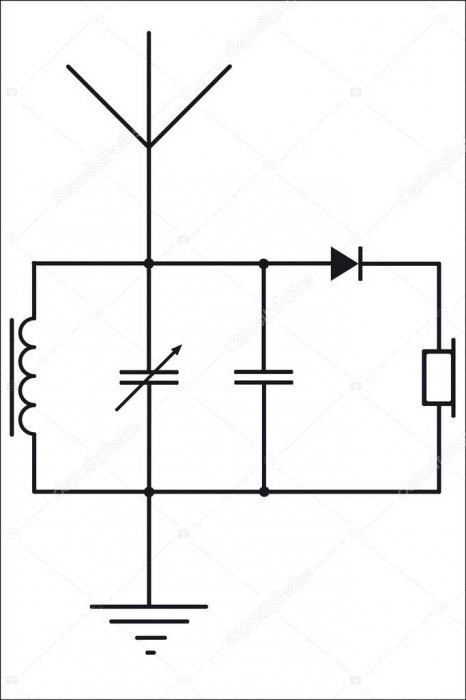
Variant circuit option
In the past scheme for introducing selectivity, you can add an inductor and a capacitor, creating an oscillatory circuit. Now, if desired, you can catch the signal of a particular radio station and even amplify it.
Tube Regenerative Shortwave Receiver
Tube radio receivers, the circuit of which is quite simple, are made to receive signals from amateur stations at short distances - to the ranges from VHF (ultra-short-wave) to LW (long-wave). Finger batteries work on this circuit. They are best generated on VHF. And the resistance of the anode load removes the low frequency. All details are shown in the diagram, only coils and a choke can be considered homemade. If you want to receive television signals, then the L2 coil (EBF11) is composed of 7 turns with a diameter of 15 mm and a wire of 1.5 mm. For an amateur receiver, 5 turns are suitable.
Direct Transistor Radio with Two Transistors
The circuit contains a magnetic antenna and a two-stage bass amplifier - this is a custom input oscillatory circuit of the radio receiver. The first stage is an RF modulated signal detector. The inductor is wound in 80 turns with a PEV-0.25 wire (from the sixth turn there is a tap from the bottom according to the diagram) on a ferrite rod with a diameter of 10 mm and a length of 40.
Such a simple radio circuit is designed to recognize powerful signals from nearby stations.
Super-regenerative device on the FM bands
The FM receiver, assembled according to the model of E. Solodovnikov, is simple to assemble, but has high sensitivity (up to 1 μV). Such devices are used for high-frequency signals (more than 1 MHz) with amplitude modulation. Due to the strong positive feedback, the cascade gain increases to infinity, and the circuit switches to the generation mode. For this reason, self-excitation occurs. To avoid it and use the receiver as a high-frequency amplifier, set the coefficient level and, when it reaches this value, sharply reduce it to a minimum. To constantly monitor the gain, you can use a sawtooth pulse generator, or you can make it easier.
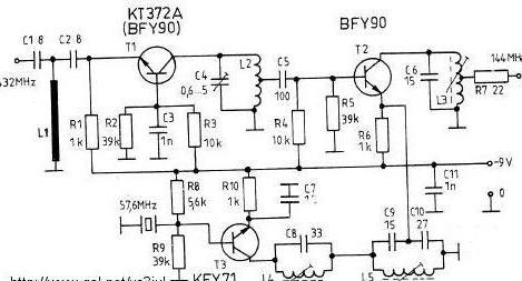
In practice, the amplifier itself often acts as a generator. Using filters (R6C7) that emit low-frequency signals, the passage of ultrasonic vibrations to the input of the subsequent ULF stage is limited. For FM signals of 100-108 MHz, the L1 coil is converted into a half-turn with a cross section of 30 mm and a linear part of 20 mm with a wire diameter of 1 mm. And the L2 coil contains 2-3 turns with a diameter of 15 mm and a wire with a cross section of 0.7 mm inside the half-turn. Receiver amplification is possible for signals from 87.5 MHz.
Microchip device
The HF radio, the circuit of which was developed in the 70s, is now considered the prototype of the Internet. Shortwave signals (3-30 MHz) travel vast distances. It’s easy to set up the receiver to listen to the broadcast in another country. For this, the prototype was called the world radio.
Simple HF receiver
A simpler radio circuit is devoid of a microcircuit. It covers the range from 4 to 13 MHz in frequency and up to 75 meters in length. Food - 9 V from the Krona battery. A mounting wire can serve as an antenna. The receiver works on headphones from the player. The high-frequency tract is built on transistors VT1 and VT2. Due to the capacitor C3, a positive reverse charge arises, regulated by the resistor R5.
Modern radios
Modern devices are very similar to Soviet radios: they use the same antenna on which weak electromagnetic waves arise. High-frequency oscillations from different radio stations appear in the antenna. They are not used directly for signal transmission, but carry out the work of the subsequent circuit. Now this effect is achieved using semiconductor devices.
The receivers were widely developed in the middle of the 20th century and since then have been continuously improving, despite replacing them with mobile phones, tablets and televisions.
The general arrangement of radios has changed slightly since Popov. We can say that the circuits are very complicated, microchips and transistors were added, it became possible to receive not only an audio signal, but also to build in a projector. So receivers have evolved into televisions. Now, if you wish, you can integrate anything you like into your device.