In electromechanics, there are many drives that work with constant loads without changing the speed of rotation. They are used in industrial and domestic equipment such as fans, compressors and others. If the nominal characteristics are unknown, then the formula for the power of the electric motor is used for calculations. Parameter calculations are especially relevant for new and little-known drives. Calculation is carried out using special coefficients, as well as on the basis of accumulated experience with similar mechanisms. Data is necessary for the proper operation of electrical installations.
What is an electric motor?
An electric motor is a device that converts electrical energy into mechanical energy. The operation of most units depends on the interaction of the magnetic field with the rotor winding, which is expressed in its rotation. They function from DC or AC power sources. A battery, an inverter or an electrical outlet can act as a power supply. In some cases, the engine works in reverse order, that is, converts mechanical energy into electrical energy. Such installations are widely used in power plants operating from the flow of air or water.
Electric motors are classified by type of power source, internal design, application and power. Also, AC drives can have special brushes. They operate from a single-phase, two-phase or three-phase voltage, have air or liquid cooling. AC motor power formula
P = U x I,
where P is power, U is voltage, I is current strength.
General purpose drives with their dimensions and characteristics are used in industry. The largest engines with a capacity of more than 100 megawatts are used in power plants of ships, compressor and pumping stations. Smaller sizes are used in household appliances like a vacuum cleaner or fan.
Electric motor design
The drive includes:
- Rotor.
- Stator.
- Bearings.
- Air gap.
- Winding.
- Switch.
The rotor is the only moving part of the drive that rotates around its axis. The current passing through the conductors forms an induction disturbance in the winding. The generated magnetic field interacts with the permanent magnets of the stator, which drives the shaft. They are calculated according to the electric motor power formula for current, for which the efficiency and power factor are taken, including all the dynamic characteristics of the shaft.
The bearings are located on the rotor shaft and facilitate its rotation around its axis. The outer part they are attached to the engine housing. A shaft passes through them and exits. Since the load goes beyond the working area of the bearings, it is called overhang.
The stator is a fixed element of the electromagnetic circuit of the motor. May include winding or permanent magnets. The stator core is made of thin metal plates called an anchor pack. It is designed to reduce energy loss, which often happens with solid rods.
Air gap - the distance between the rotor and the stator. A small gap is effective, as it affects the low coefficient of operation of the electric motor. The magnetization current increases with the size of the gap. Therefore, they always try to make it minimal, but to a reasonable extent. Too small a distance leads to friction and weakening of the locking elements.
The winding consists of copper wire assembled into a single coil. Usually placed around a soft magnetized core consisting of several layers of metal. Induction field perturbation occurs at the moment of passage of current through the winding wires. At this point, the installation goes into configuration mode with explicit and implicit poles. In the first case, the magnetic field of the installation creates a winding around the pole piece. In the second case, the slots of the pole end of the rotor are distributed in a distributed field. The motor with shielded poles has a winding that inhibits magnetic disturbance.
The switch is used to switch the input voltage. Consists of slip rings located on the shaft and isolated from each other. The armature current is supplied to the contact brushes of the rotary switch, which leads to a change in polarity and causes the rotor to rotate from pole to pole. In the absence of voltage, the motor stops spinning. Modern installations are equipped with additional electronic means that control the rotation process.
Operating principle
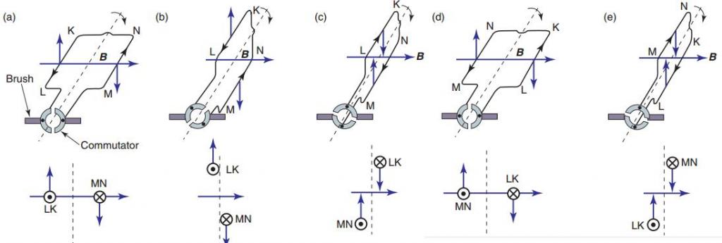
According to the law of Archimedes, the current in the conductor creates a magnetic field in which the force F1 acts. If a metal frame is made from this conductor and placed in a field at an angle of 90 °, then the edges will experience forces directed in the opposite direction relative to each other. They create a torque about the axis, which begins to rotate it. The turns of the anchor provide constant torsion. The field is created by electric or permanent magnets. The first option is made in the form of a coil winding on a steel core. Thus, the frame current generates an induction field in the electromagnet winding, which generates an electromotive force.
Let us consider in more detail the operation of induction motors using the example of units with a phase rotor. Such machines operate on alternating current with an arm rotation speed not equal to the magnetic field ripple. Therefore, they are also called induction. The rotor is driven by the interaction of an electric current in the coils with a magnetic field.
When there is no voltage in the auxiliary winding, the device is at rest. As soon as an electric current appears at the stator contacts, a constant magnetic field is formed in space with a ripple + and -. It can be represented as the following formula:
n ol = n arr = f 1 × 60 ÷ p = n 1
Where:
n CR - the number of revolutions that makes a magnetic field in the forward direction, rpm
n arr is the number of field revolutions in the opposite direction, rpm;
f 1 - the frequency of the ripple of the electric current, Hz;
p is the number of poles;
n 1 is the total number of revolutions per minute.
Undergoing pulsations of the magnetic field, the rotor receives the initial motion. Due to the heterogeneity of the impact of the flow, it will develop torque. According to the law of induction, an electromotive force is generated in the short-circuited winding, which generates a current. Its frequency is proportional to the slip of the rotor. Due to the interaction of an electric current with a magnetic field, a shaft torque is created.
For performance calculations, there are three power formulas for an induction motor. Phase shift is used
S = P ÷ cos (alpha), where:
S is the total power measured in volts-amperes.
P is the active power indicated in watts.
alpha is the phase shift.
Under full power is meant a real indicator, and under active - calculated.
Types of electric motors
According to the power source, the drives are divided into operating from:
- Direct current.
- Alternating current.
According to the principle of their work, they, in turn, are divided into:
- Collector.
- Valve
- Asynchronous.
- Synchronous.
Valve motors do not belong to a separate class, since their device is a variation of the collector drive. Their design includes an electronic converter and a rotor position sensor. Usually they are integrated with the control board. At their expense, a coordinated switching of the armature occurs.
Synchronous and asynchronous motors operate exclusively on AC. Speed control is done using sophisticated electronics. Asynchronous are divided into:
- Three phase.
- Biphasic.
- Single phase.
The theoretical formula for the power of a three-phase electric motor when connected to a star or triangle
P = 3 * U f * I f * cos (alpha).
However, for linear values of voltage and current, it looks like
P = 1.73 × U f × I f × cos (alpha).
This will be a real indicator of how much power the engine takes from the network.
Synchronous are divided into:
- Stepping.
- Hybrid
- Inductive.
- Hysteresis.
- Reactive.
In their design, stepper motors have permanent magnets, so they are not assigned to a separate category. The operation of the mechanisms is controlled using frequency converters. There are also universal motors that operate on direct and alternating current.
General characteristics of engines
All motors have common parameters that are used in the formula for determining the power of an electric motor. Based on them, you can calculate the properties of the machine. In different literature, they may be called differently, but they mean the same thing. The list of such parameters includes:
- Torque.
- Engine power.
- Efficiency.
- Nominal number of revolutions.
- The moment of inertia of the rotor.
- Rated voltage.
- Electrical time constant.
The above parameters are necessary, first of all, to determine the effectiveness of electrical installations operating due to the mechanical force of the engines. The calculated values give only an approximate idea of the actual characteristics of the product. However, these indicators often use electric motor power in the formula. It is she who determines the performance of machines.
Rotational moment
This term has several synonyms: torque, engine torque, torque, torque. All of them are used to designate one indicator, although from the point of view of physics these concepts are not always identical.
In order to unify the terminology, standards were developed that lead to a single system. Therefore, in the technical documentation the phrase "torque" is always used. It is a vector physical quantity that is equal to the product of the vector values of force and radius. The radius vector is drawn from the axis of rotation to the point of applied force. From the point of view of physics, the difference between torque and torque is the point of application of force. In the first case, this is an internal effort, in the second - external. Measured in Newton meters. However, in the electric motor power formula, torque is used as the main value.
It is calculated as
M = F × r, where:
M - torque, Nm;
F is the applied force, H;
r is the radius, m
To calculate the rated torque of the drive, use the formula
Mnom = 30P nom ÷ pi × n nom , where:
P nom - rated power of the electric motor, W;
n nom - nominal speed, min -1 .
Accordingly, the formula for the rated power of the electric motor needs to look like this:
Pnom = M nom * pi * n nom / 30.
Usually all specifications are indicated in the specification. But it happens that you have to work with completely new installations, information about which is very difficult to find. To calculate the technical parameters of such devices take the data of their analogues. Also, only the nominal characteristics that are given in the specification are always known. Real data must be calculated independently.
Engine power
In a general sense, this parameter is a scalar physical quantity, which is expressed in the rate of consumption or energy conversion of the system. It shows what kind of work the mechanism will do in a given unit of time. In electrical engineering, a characteristic displays useful mechanical power on a central shaft. To indicate the indicator, use the letter P or W. The main unit of measure is Watt. The general formula for calculating the power of an electric motor can be represented as:
P = dA ÷ dt, where:
A - mechanical (useful) work (energy), J;
t is the elapsed time, sec.
Mechanical work is also a scalar physical quantity, expressed by the action of force on the object, and depending on the direction and movement of this object. It is a product of the force vector on the path:
dA = F × ds, where:
s - distance traveled, m
It expresses the distance that the point of applied force will overcome. For rotational movements, it is expressed as:
ds = r × d (teta), where:
teta - angle of rotation, glad.
Thus, it is possible to calculate the angular frequency of rotation of the rotor:
omega = d (teta) ÷ dt.
From it follows the formula for the power of the electric motor on the shaft: P = M × omega.
The efficiency of the electric motor
Efficiency is a characteristic that reflects the efficiency of the system when converting energy into mechanical energy. It is expressed by the ratio of useful energy to spent. According to a unified system of units of measurement, it is designated as "eta" and is a dimensionless value, calculated in percent. Efficiency formula of an electric motor through power:
eta = P 2 ÷ P 1 , where:
P 1 - electric (supplied) power, W;
P 2 - useful (mechanical) power, W;
It can also be expressed as:
eta = A ÷ Q × 100%, where:
A - useful work, J;
Q - expended energy, J.
More often, the coefficient is calculated by the formula of the power consumption of the electric motor, since these indicators are always easier to measure.
The decrease in the efficiency of the electric motor occurs due to:
- Electrical losses. This occurs as a result of heating the conductors from the passage of current through them.
- Magnetic loss. Due to excessive magnetization of the core, hysteresis and eddy currents appear, which is important to consider in the power formula of the electric motor.
- Mechanical losses. They are associated with friction and ventilation.
- Additional losses. They appear due to harmonics of the magnetic field, since the stator and rotor have a gear shape. Also in the winding there are higher harmonics of the magnetomotive force.
It should be noted that the efficiency is one of the most important components of the formula for calculating the power of the electric motor, since it allows you to get the numbers closest to reality. On average, this indicator varies from 10% to 99%. It depends on the design of the mechanism.
Rated speed
Another key indicator of the electromechanical characteristics of the engine is the shaft speed. It is expressed in revolutions per minute. Often it is used in the power formula of the pump motor to find out its performance. But it must be remembered that the indicator is always different for idle and work under load. The indicator represents a physical quantity equal to the number of full revolutions over a certain period of time.
The calculated formula for the speed:
n = 30 × omega ÷ pi, where:
n is the engine speed, rpm
In order to find the power of the electric motor by the formula of the shaft speed, it is necessary to bring it to the calculation of the angular velocity. Therefore, P = M × omega will look like this:
P = M × (2pi × n ÷ 60) = M × (n ÷ 9.55), where
t = 60 seconds.
Moment of inertia
This indicator is a scalar physical quantity that reflects the measure of inertia of the rotational motion around its own axis. In this case, body mass is the value of its inertness during translational motion. The main characteristic of the parameter is expressed by the distribution of body masses, which is equal to the sum of the products of the square of the distance from the axis to the base point by the mass of the object. In the International system of units of measurement it is denoted as kg · m 2 and is calculated by the formula:
J = ∑ r 2 × dm, where
J is the moment of inertia, kg · m 2 ;
m is the mass of the object, kg.
Moments of inertia and force are interconnected by the ratio:
M - J × epsilon, where
epsilon - angular acceleration, s -2 .
The indicator is calculated as:
epsilon = d (omega) × dt.
Thus, knowing the mass and radius of the rotor, it is possible to calculate the performance parameters of the mechanisms. The motor power formula includes all of these characteristics.
Rated voltage
It is also called nominal. It represents the base voltage, represented by a standard set of voltage, which is determined by the degree of isolation of electrical equipment and the network. In fact, it may differ at different points of the equipment, but should not exceed the maximum permissible operating conditions, designed for continuous operation of mechanisms.
For conventional installations, rated voltage is understood as the calculated values for which they are provided by the developer in normal operation. The list of standard network voltage is provided in GOST. These parameters are always described in the technical characteristics of the mechanisms. :
P = U × I.
, 63 % . , . :
t e = L ÷ R.
t m t e. , .
M = M + J × (d(omega) ÷ dt),
M = 0.
:
M = J × (d(omega) ÷ dt).
- M . , , :
M = M × (1 - omega ÷ omega 0 ),
omega 0 - idle speed.
Such calculations are used in the power formula of the pump motor, when the piston stroke directly depends on the speed of the shaft.
Basic formulas for calculating engine power
To calculate the real characteristics of mechanisms, you always need to consider many parameters. First of all, you need to know what current is supplied to the motor windings: direct or alternating. The principle of their work is different, therefore, the method of calculation is different. If the simplified form of calculating the drive power looks like:
P el = U × I, where
I is the current strength, A;
U is the voltage, V;
P el - summed up electrical power. Tue
In the AC power formula, the phase shift (alpha) must also be taken into account. Accordingly, the calculations for an asynchronous drive look like:
P el = U × I × cos (alpha).
In addition to the active (failed) power, there are also:
- S - reactive, VA. S = P ÷ cos (alpha).
- Q - full, VA. Q = I × U × sin (alpha).
In the calculations, it is also necessary to take into account thermal and induction losses, as well as friction. Therefore, a simplified model of the formula for a DC motor looks like:
P el = P fur + Rtep + Rind + Rtr , where
Rmeh - net power generated, W;
Rtep - losses due to heat generation, VT;
Rind - the cost of the charge in the induction coil, W;
RT - losses due to friction, W.
Conclusion
Electric motors are used in almost all areas of human life: in everyday life, in production. For the correct use of the drive, it is necessary to know not only its nominal characteristics, but also real ones. This will increase its efficiency and reduce costs.