Most LCD and plasma TVs have a VGA connector, or, as it is also called, a D-sub. In addition, it is used in computer technology to connect the system unit and the monitor. The abbreviation VGA comes from the name of computer video adapters. VGA connector developed by Canon. At first it was the smallest in comparison with other similar connectors.
general information
This output of analog signals to the monitor is familiar to almost every user of a personal computer. VGA connector Designed to connect any modern TV or monitor. The interface in question can be found both on the latest equipment, and on a rather old one. In modern laptops, in order to minimize the space occupied by the connector on the device case, manufacturers most often do not use screw fasteners of the cable to the connector, so the user must be extremely careful when moving the laptop.
Interface Description
There are several types of execution of this connector. The VGA connector is just a special case of the entire series, invented by Canon. Each connector is labeled with the first letter indicating the type of series (D). The second letter is the number of pins, and the number following them indicates the number of pins that are actually used in the connector (A-15, B-25, C-37, D-50, E-9). The last letter means the type of connector (M - "mother", F - "father"). In modern monitors and televisions, as well as in video cards of laptops and computers, type A connectors are used, which corresponds to 15 contacts.
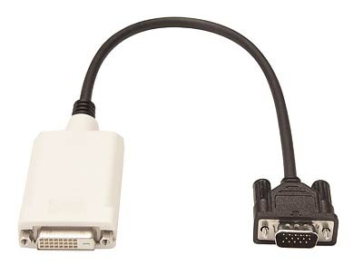
In order to transfer the image through this interface, use the RGB scheme. VGA connector with the help of special adapters it can be combined with other interfaces, for example, SCART. More complex is considered an adapter to the DVI interface. In computer stores you can still purchase a DVI-VGA cable, and this interface is represented by both types - DVI-I and DVI-D. In addition to the main contacts responsible for transmitting video signals, service information between the TV and the signal source is transmitted through the VGA connector, for example, data on the number of colors, screen resolution , etc.
VGA connector: pinout
So, we present to your attention the wiring of such a connector, at the same time we will decipher the purpose of each output:
1. The red channel is 75 Ohms, 0.7V.
2. Green channel - 75 Ohms, 0.7V.
3. Blue channel -75 Ohm, 0.7V.
4. The second identification bit.
5. Common wire.
6. "Earth" of the red channel.
7. The "Earth" of the green channel.
8. The "earth" of the blue channel.
9. The key.
10. Earth synchronization.
11. Zero identification bit.
12. A single identification bit, or DDC data.
13. Composite or line synchronization.
14. Frame synchronization.
15. DDC ticks, or third identification bit.
Conclusion
It should be noted that audio information through the mentioned type of connection is not transmitted. This can cause additional difficulties when synchronizing sound and image. After all, TVs usually do not have additional audio inputs compatible with the VGA-connector. The easiest way to synchronize the two signals is to use a separate speaker system.