Computers cannot work without electricity. To charge them, special devices called power supplies are used. They receive alternating current voltage from the network and convert it to direct current. Devices can produce a huge amount of energy in a small form factor, have built-in overload protection. The issued parameters are incredibly stable, and the quality of the direct current is ensured even at high loads. When there is such an extra device, it is reasonable to use it for many household tasks, for example, by converting it into a charger from the computer’s power supply.
Desktop Power Supply Design
The block has the form of a metal box with a width of 150 mm x 86 mm x 140 mm. As standard, it is mounted inside the PC case with four screws, a switch and a socket. This design allows air to enter the cooling fan of the power unit (PSU). In some cases, a voltage selector switch is installed, allowing the user to select indicators. For example, in the United States there is an internal power source operating at a nominal voltage of 120 volts.
A computer PSU consists of several components inside: a coil, capacitors, an electronic board for regulating current, and a fan for cooling. The latter is the main cause of failure for power supplies (IP), which must be taken into account when installing the charger from the atx computer power supply.
Types of power supply for a personal computer
IPs have a specific power indicated in watts. The standard unit, as a rule, is capable of providing about 350 watts. The more components installed on your computer: hard drives, CD / DVD drives, tape drives, fans, the more energy is required from the power source.
Experts recommend using a power supply unit that provides more power than the computer needs, since it will operate in a constant “underload” mode, which will increase the machine’s life due to a decrease in thermal effects on its internal components.
There are 3 types of IP:
- AT Power Supply - used on very old PCs.
- ATX power supply - still used on some PCs.
- Power Supply ATX-2 - commonly used today.
PSU parameters that can be used when creating a charger from a computer power supply:
- AT / ATX / ATX-2: +3.3 V.
- ATX / ATX-2: +5 V.
- AT / ATX / ATX-2: -5 V.
- AT / ATX / ATX-2: +5 V.
- ATX / ATX-2: +12 V.
- AT / ATX / ATX-2: -12 V.
Motherboard connectors
There are many different power connectors in the IP. They are designed in such a way that you can’t make a mistake when installing them. To make the charger from the computer’s power supply, the user will not need to choose the right cable for a long time, as it simply does not fit in the connector.
Types of connectors:
- P1 (PC / ATX connector). The main task of the power supply unit (PSU) is to provide power to the motherboard. This is done through 20-pin or 24-pin connectors. The 24-pin cable is compatible with a 20-pin motherboard.
- P4 (EPS connector). Previously, the conclusions of the motherboard were not enough to provide processor power. With an overclocking graphics processor reaching 200 watts, it was possible to provide power directly to the processor. Currently, it is P4 or EPS, which provide sufficient processor power. Therefore, the alteration of the computer power supply to the charger is economically feasible.
- PCI-E slot (6-pin 6 + 2). The motherboard can provide a maximum of 75 watts through the PCI-E interface slot. A faster dedicated graphics card requires much more power. To solve this problem, a PCI-E slot was introduced.
Cheap motherboards have a 4-pin connector. More expensive overclocking motherboards have 8-pin connectors. Additional ones provide excessive processor power during overclocking.
Most power supplies have two cables: 4-pin and 8-pin. Only one of these cables must be used. You can also split the 8-pin cable into two segments to provide backward compatibility with cheaper motherboards.
Graphics Card Power
The left 2 pins of the 8-pin connector (6 + 2) on the right are disconnected for backward compatibility with 6-pin graphics cards. A 6-pin PCI-E connector can supply an additional 75W per cable. If the graphics card contains one 6-pin connector, it can be up to 150 watts (75 watts from the motherboard + 75 watts from the cable).
More expensive graphics cards require an 8-pin (6 + 2) PCI-E slot. With 8 pins, this connector can provide up to 150 watts per cable. A video card with one 8-pin connector can be up to 225 W (75 W from the motherboard + 150 W from the cable).
Molex, a 4-pin peripheral connector, is used when creating a charger from the computer’s power supply. These contacts work for a very long time, they can supply 5V (red) or 12V (yellow) to peripheral devices. In the past, these connections were often used to connect hard drives, CD-ROM players, etc.
Even Geforce 7800 GS graphics cards come with Molex. However, their power consumption is limited, so most of them have now been replaced by PCI-E cables and SATA cables. All that remains is powered fans.
Accessories Connector
The SATA connector is a modern replacement for the obsolete Molex. All modern DVD players, hard drives and SSDs are powered by SATA. The Mini-Molex / Floppy connector is completely outdated, but some PSUs still come with a mini-molex connector. They were used to power floppy drives up to 1.44 MB of data. Basically, they are replaced today with a USB drive.
6-pin Molex-PCI-E adapter to power the video card.
Using the adapter 2x-Molex-1x PCI-E 6-pin, you first need to make sure that both Molex are connected to different cable voltages. This reduces the risk of overloading the power source. With the introduction of ATX12 V2.0, changes were made to the 24-pin system. Older ATX12Vs (1.0, 1.2, 1.2, and 1.3) used a 20-pin connector.
There are 12 versions of the ATX standard in total, but they are so similar that the user does not need to worry about compatibility when installing the charger from the computer’s power supply. To ensure backward compatibility, most modern sources allow you to disconnect the last 4 pins of the main connector. It is also possible to create advanced compatibility using an adapter.
Computer voltage
A computer requires three types of constant voltage. 12 volts is needed to supply voltage to the motherboard, graphics cards, for fans, processor. USB ports require 5 volts, while the CPU itself uses 3.3 volts. 12 volts are also applicable to some smart fans. The electronic board in the power supply unit is responsible for sending the converted electricity through special cable sets to power the devices inside the computer. Using the above components, AC voltage is converted to pure DC.
Almost half of the work performed by the power supply is carried out using capacitors. They store energy that will be used for continuous work flow. When making a battery charger from the computer’s power supply, the user must be careful. Even if the computer is turned off, there is a possibility that electricity will be stored inside the power supply in capacitors, even a few days after the shutdown.
Color codes for cable sets
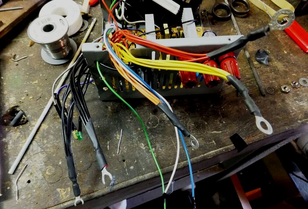
Inside the power supply, the user sees a lot of cable sets coming out with different connectors and different numbers. Power cable color codes:
- Blacks are used to provide current. Every other color must be connected to a black wire.
- Yellow: + 12V.
- Red: + 5 V.
- Blue: -12V.
- White: -5V.
- Orange: 3.3V.
- Green test lead for checking DC voltage.
- Violet: + 5 Standby.
The output voltages of the computer's power source can be measured using an appropriate multimeter. But because of the higher risk of short circuit, the user should always connect a black cable with black on the multimeter.
Power plug
The hard drive wire (whether it is an IDE or SATA) has four cores attached to the connector: yellow, two black in a row, and red. Both 12V and 5V are simultaneously used on the hard drive. 12V feeds moving mechanical parts, and 5V supplies electronic circuits. Thus, all of these cable sets are equipped with 12V and 5V cables at the same time.
The electrical connectors on the motherboard for processors or chassis fans have four legs that support the motherboard for 12 V or 5 V fans. In addition to black, yellow and red, other colored wires can only be seen in the main connector, which goes directly to the motherboard socket. These are purple, white or orange cables that are not used by consumers to connect peripheral devices.
Turning on ATX without a computer
If you want to make a car charger from the computer's power supply, you need to test it. You will need a paper clip and about two minutes of time. If you need to connect the power source back to the motherboard, you just need to remove the paper clip. No changes from using a paper clip in it will happen.
Procedure:
- Find the green wire in the cable tree from the power supply.
- Follow it to the 20 or 24 pin ATX connector. The green wire, in a sense, is the “receiver”, which is needed to supply power to the power supply. Between it there are two black ground wires.
- Place the paper clip in the pin with the green wire.
- Place the other end in one of the two black ground wires next to the green. It doesn’t matter which one will work.
Although the paper clip will not shock, it is not recommended to touch its metal part when it is energized. If you want to leave a paper clip for an indefinite period, you need to wind it with electrical tape.
Creating a Charger
If you start to make a do-it-yourself charger from the computer’s power supply, take care of the safety of work. The source of the threat is capacitors that carry a residual charge of electricity that can cause significant pain and burns. Therefore, you need to not only make sure that the IP is reliably disconnected, but also wear insulation gloves.
After opening the PSU, they make an assessment of the workspace and make sure that there will be no problems with clearing the wires.
They preliminarily think over the source design, measuring with a pencil where the holes will be in order to cut off the wires of the required length.
Sort the wires. This will be necessary: black, red, orange, yellow and green. The rest are redundant, so they can be cut off on the circuit board. Green indicates power on after standby. It simply solders to the grounding black wire, which will ensure that the PSU is turned on without a computer. Next, you need to connect the wires to 4 large clips, one for each set of colors.
After that, you need to group 4-wire colors together and cut them to the required length, remove the insulation and connect at one end. Before drilling holes, you need to take care of the chassis circuit board so that it is not contaminated with metal chips.
In most PSUs, the circuit board cannot be completely removed from the chassis. In this case, it must be carefully wrapped in a plastic bag. After drilling, it is required to process all rough spots and wipe the chassis with a cloth from debris and plaque. Then install the fixing posts using a small screwdriver and terminals, securing them with pliers. After that, close the power supply and mark the voltage on the panel with a marker.
Experts recommend installing rubber feet on the bottom of the device so that it does not lie on the floor.
Charging the car battery from an old PC
This device will help the car enthusiast in a difficult situation when you urgently need to charge the car battery, without having a standard device, but using only a regular PC power supply. Experts do not recommend constantly using the car charger from the computer's power supply, since the voltage of 12 V does not reach the required level when charging the battery. It should be 13 V, but as an emergency option it can be used. To amplify the voltage where it used to be 12V, you need to change the resistor to 2.7kOhm on the tuning resistor installed on the additional power supply board.
Since the power sources have capacitors that retain electricity for a long time, it is advisable to discharge them using a 60 W incandescent lamp. To attach the lamp, use the two ends of the wire to connect to the terminals of the cover. The backlight slowly goes out, discharging the cover. Closing the terminals is not recommended, as this will result in a large spark and may damage the circuit board tracks.
The procedure for making a do-it-yourself charger from the computer’s power supply starts with the removal of the top panel of the power supply. If a 120 mm fan is installed on the top panel, disconnect the 2-pin connector from the circuit board and remove the panel. It is required to cut the output cables from the power source using pliers. Do not throw them away, it is better to use them repeatedly for non-standard tasks. For each bonding post, leave no more than 4–5 cables. The rest can be cut off on a printed circuit board.
The wires of the same color are connected and secured using cable ties. The green cable is used to turn on the direct current IP. It is soldered to the GND terminals or connected to the black wire from the bundle. Next, measure the center of the holes on the top cover, where the fixing posts should be fixed. You need to be especially careful if a fan is installed on the top panel, and the gap between the edge of the fan and the IP is small for the fixing pins. In this case, after marking the central points, you need to remove the fan.
After that, you need to attach the fixing racks to the top panel in the order: GND, +3.3 V, +5 V, +12 V. Using a stripper for wires, the insulation of the cables of each bundle is removed, the connections are soldered. Using a heat gun, the sleeves are processed over the crimp joints, after which the projections are inserted into the connecting pins and tighten the second nut.
Next, you need to return the fan to its place, connect the 2-pin connector to the socket on the circuit board, insert the panel back into the device, which may require some effort due to the bundle of cables on the crossbars and close.
Screwdriver Charger
If the screwdriver has a voltage of 12V, then the user is lucky. He can make a power source for the charger without any alterations. You will need a used or new computer PSU. It has several voltages, but it needs 12V. There are many wires of different colors. You will need yellow ones that give out 12V. Before starting work, the user must make sure that the IP is disconnected from the energy source and does not have residual voltage in the capacitors.
Now you can begin to remake the computer's power supply into a charger. To do this, connect the yellow wires to the connector. This will be a 12V output. Do the same for black wires. These are the connectors into which the charger will be connected. In the unit, the voltage of 12V is not primary, therefore a resistor is connected to the red wire of 5V. Next, connect the gray and one black wire together. This is a signal that speaks of energy supply. The color of this wire may vary, so make sure it is a PS-ON signal. This should be written on the sticker of the power supply.
After turning on the switch, the PSU should start, the fan should rotate, and the light will come on. After checking the connectors with a multimeter, you need to make sure that the unit gives out 12 V. If so, then the charger of the screwdriver from the computer's power supply is functioning correctly.
Tips experienced
In fact, there are many options for adapting the power supply for your own needs. Those who like to experiment with pleasure share their experience. .
: , , . , , ATX. AT , , , . , , , .
, . , - . . .