One of the largest manufacturers of tractors in the USSR and in modern Russia is the Vladimir Motor-Tractor Plant (VMTZ). The most famous model of the plant was a small wheeled tractor T 25, which was produced from 1966 to 2000. During this time, more than 800 thousand cars passed through the gates of the plant.
Representative of a large family
T 25 and its modifications were equipped with a D 21 two-cylinder diesel engine. The engine was developed by VMTZ designers as part of a family of engines, which included three-, four- and six-cylinder diesel engines. Technical characteristics of the D 21 engine fully corresponded to the requirements for a tractor of this class. All options were equipped with a forced air cooling system. A general view of the tractor with the D 21 engine is shown in the photo below.
Engines had wide unification in many details. Identical were the details of the cylinder-piston group and the gas distribution mechanism (with the exception of the camshafts).
Carter
The main part of the D 21 engine is a cast-iron crankcase (the so-called block crankcase), closed from below with a stamped oil pan. Inside the crankcase are three bearings of the crankshaft, as well as a pair of bearings of the camshaft and balancing shafts. To increase rigidity, the axis of the crankshaft bearings is located above the lower plane of the block. Inside the block there are channels for supplying oil from the gear pump to the bearings.
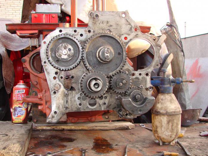
A cast engine flywheel housing is attached to the rear of the crankcase. At the front of the motor are gears for camshaft drive and auxiliary units. The gear block is closed by a removable cover. All main engine assemblies are mounted on the crankcase or the front and rear engine covers.
On the left side of the engine (along the tractor) there is a pump for supplying fuel and pipelines for supplying fuel to the pump and to the nozzles in the cylinder heads. On the same side are the air intake and exhaust manifolds. On the intake manifold there is a glow plug used to heat the air. Additional heating is used to facilitate starting the engine at low air temperatures.
On the frontal part of the engine there is a throat for oil filling, an axial fan inlet and an hour meter. A generator is mounted on the same axis as the fan. The entire assembly is secured with a clamp to the gear block cover. The drive is carried out using a belt drive from the crankshaft. On the shaft pulley there are marks of opposite dead spots in the first cylinder (designated as TDC and BDC) and a mark of the beginning of fuel injection into the first cylinder (mark T). An oil dipstick and a filter system for cleaning fuel are also mounted on the front of the D 21 engine.
A decompressor is installed on the right side of the motor, which serves to facilitate starting the engine. This mechanism connects the cylinder cavity with the atmosphere and can be used to emergency stop the diesel engine. On the same side, fuel injection nozzles are installed in the cylinder heads. The cylinders are closed by a casing into which air is pumped for cooling. An electric starter is installed at the bottom of the engine closer to the flywheel housing.
Cylinder
There are two holes on the top of the unit for installing individual cylinders. On the side of each there is a pair of additional holes for the valve follower rods.
The cylinders are made of cast iron and equipped with a mounting flange and eighteen thin-walled cooling fins. Between the ribs there is a gap of 8 mm for the circulation of cooling air. The ribs are asymmetrical in circumference.
The fin is shorter on the fan side and longer on the opposite side. This is done to more evenly cool the cylinder. From the front and rear ends, the ribs are made short to reduce the distance between the cylinders and the overall length of the motor as a whole. Also, cuts for mounting studs are made on the ribs.
Since the material of the cylinder is a special wear-resistant cast iron, the mirror is made directly on the inner surface. When worn or damaged, the cylinder is simply replaced with a new one.
Cylinder head
Each cylinder of the D 21 engine has an individual aluminum head in which the inlet and outlet valves, the decompressor hole and the nozzle are located.
The head and cylinder are fastened with four studs screwed into the body of the block. Heads, like cylinders, are interchangeable. For cooling, the head is equipped with eleven ribs. In the upper part of the head there are guide bushings for valves and studs for the axis of the rocker arm of the valve actuator. Heat-resistant cast iron valve seats are pressed into the lower part.
Inside the head there are intake and exhaust channels that go to the left side. Intake and exhaust manifolds are attached to these channels on studs.
Pistons
Aluminum pistons have a combustion chamber in their design. The chamber has a spherical shape and is made in the piston bottom.
To ensure reliable operation, the piston has three compression rings as well as two oil scraper rings. In the grooves under the oil scraper rings , holes are made for draining the oil removed by the rings.
The piston has a different diameter in length to reduce the likelihood of sticking during operation. The upper, more thermally loaded part of the piston has a smaller diameter than the piston skirt. This solution allows you to equalize the thermal expansion of the part in the process.