It is a common situation when, after a sudden power outage, the computer stops showing signs of life. A quick check shows that the cause of this is a malfunction of the power supply. Unfortunately, after a call to the service center, it becomes clear that replacing it will cost a decent amount. Moreover, due to the unique design of the case, the device of the required size is not available. Fortunately, repairing a computer power supply is not complicated. Although different models look different in appearance, according to user reviews, inside they often use the same electronics.
This article is intended to help repair a faulty power supply for any PC.
Basic concepts
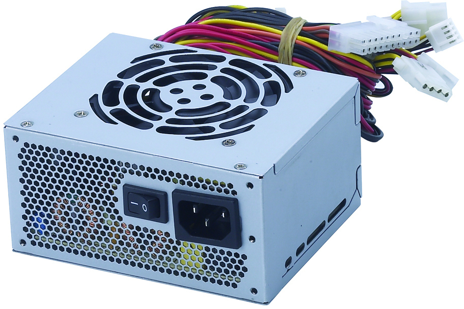
The computer power supply is a metal box installed inside the PC. It provides power to the motherboard and various peripherals. How to find out the power supply on a computer? It is easily identified by a warning sticker on the case with the inscription: “ATTENTION! Hazardous Area ”(or similar high voltage warning). On the back of the power source is an AC connector through which the PC connects to a wall outlet. Often there is an additional connection that is used by some monitors. Most PSUs also have a switch that allows you to work in 110 and 220 V. networks. A typical power supply of old PCs (AT) provides 4 DC output voltages: +5, +12, -5 and -12 volts, and the ATX standard added + 3.3 V. They are available through various types of connectors. The color of the wire of the computer power supply determines the voltage and its use.
For descriptive reasons, we decided to arrange the color coding in a table (see below).
Color | Voltage | Range, In | Resistance, Ohm | Using |
Red | +5 | +4.75 - +5.25 | > 100 | motherboard, adapters, drives |
White | -5 | -4.75 - -5.25 | > 100 | logic |
Yellow | +12 | +9 - +15 | > 250 | disk drives, RS-232 serial port, fans, adapters |
Blue | -12 | -9 - -15 | > 250 | RS-232 port, fans |
Orange (AT) Gray (ATX) | no and +5 | 0 and + 2.4– +6 | 1000 | nutrition status |
Orange (ATX) | +3.3 | +3.14 - 3.47 | > 5 | motherboard |
The black | 0 | 0 | 0 | Earth |
According to user reviews, the colors make it easy to figure out the pinout of different types of computer power supplies.
Where to start?
Often, malfunctions of a computer's power supply are very simple and easy to fix. User reviews recommend first of all to determine whether the voltage from the network to the PC. Oddly enough, the first thing to do is look under the table and check if the computer is connected. If this is the case, then plug in the other outlet (they also sometimes fail).
Having done this, you need to unplug the power cord from the back of the computer and make sure that the voltage reaches it. This can be done using a multimeter or a simple tester with a neon lamp. If there is no power, and the connection is made through an extension cable with surge protection, it may be his fault. To check it, you need to unplug the plug from the power strip and insert it into the wall. If the PC works, then the problem is in the extension cord. User reviews advise checking the fuse and circuit breaker. Another element that must be tested before dismantling the computer is the surge protector cord.
Internal organization
If all of the above does not resolve the problem, then it's time to remove the cover of the power supply. Most models are attached to the back of the PC with 5–6 screws. Before moving on, you must carefully read the safety instructions.
User reviews recommend paying attention to the power switch. Unfortunately, at this stage it may not be available. Many power supplies have a built-in switch. However, in tower-type cases, it is located on the front panel and is connected to the power supply unit with 4 wires. All you need to do is disconnect them and check it with an ohmmeter. To test the circuit breaker under load (i.e., bypass it), you can short-circuit the power wires using 2 insulated jumpers and connect the computer to the network. It is necessary to ensure that the jumpers do not touch anything else.
Next, you need to check what DC power is on the computer's power supply. If before this, the AC wires from the front panel switch were disconnected, they will have to be restored. With the main switch turned off, you must find a free power connector (preferably 5 ”drives) or disconnect a busy one. Do not disconnect the hard drive, as it will be needed as a load throughout the test. You need to turn on the PC and measure the voltages of + 5-volt (red) and + 12-volt (yellow) lines with a voltmeter (using the black ground wire). You must make sure that the real values fall within the range indicated in table 1. If they fall outside the acceptable range, then turn off the system and disconnect the connected devices one at a time, starting with floppy drives. In this case, each time you need to measure the voltage of the +5 V and +12 V. lines. This will let you know if the problem is related to a specific device. In this case, do not forget to turn off the PC every time.
When a hard disk (s) is connected, it is necessary to disconnect the power connectors of the motherboard.
Finally, it's time to deal with the unlikely possibility of a hard drive malfunction. If there are several, then HDD should be disabled one at a time. Reaching the last one, it is necessary to establish a dummy load instead, for example, 2 lamps.
Before starting the power supply without a computer, users recommend always checking for the load. Otherwise, the output voltage rises so much that the protection trips and turns off the device. In addition, it may be necessary to ground the Power on pin (marked in green). In the 24-pin pinout of the computer's power supply, this is the 16th pin, and in the 20-pin pin, it is the 14th.
If the malfunction is still not resolved, reviews recommend proceeding with dismantling.
Parsing and inspection
Since all the connectors are already disconnected, it is enough to remove the mounting screws and pull out the computer’s power supply unit from the case with your own hands. In the case of the tower, it is likely that you will run into obstacles such as adapter cards, signal cables for drives, and support brackets. If there is a user manual, then it will prompt the necessary procedure. Otherwise, you have to rely only on yourself. In any case, you need to record how everything was connected and store the screws with the objects that they held.
If the PSU was connected to the network a few minutes ago, then the large capacitors in the high-voltage section, most likely, will still have a charge. In this case, before continuing, you must leave it for a while. The device of the computer power supply is individual, but, as a rule, its design provides protection for internal electronics. Unscrewing the power supply, you should be careful about wires, switches and sharp edges. If you need to disconnect something, it is better to write down how to reconnect it.
Electronics should be well inspected for burnt, deformed parts, which may indicate a malfunction. If there is a built-in power switch, then it is time to check it. After this, the fuse integrity must be determined. If in doubt, it is better to use a multimeter (in the X100 range). If the fuse is blown, then before moving on, replace it with a new one of the same type and rating. Perhaps the problem is related to metal fatigue or mechanical damage. To verify that this helped, you can by connecting a dummy load to one of the drive connectors and supply power.
If nothing happens, then you can remove the load and proceed with the resistance test procedure. If the fuse blows with an explosion, you must go to the repair section of the high-voltage part of the power supply.
Resistance test
Referring to Table 1, you should test the resistance of the elements of the power supply (without a computer). Before measuring, it is necessary to observe the polarity of the multimeter, that is, when checking a negative source, connect the red wire to the ground and wait until the filter capacitors are charged. The resistance values given are representative, so do not worry if the actual readings differ.
But if the resistance value is abnormally high or low, then this indicates a problem. According to user reviews, 50 ohms or higher on the 5 and 12 V lines means that the output is probably good. Resistance of 40 ohms or less usually indicates a short circuit in the rectifier diodes. The 5-volt line is most prone to malfunction because it carries the heaviest load (typically 20 A). Extremely high resistance indicates a broken wire or track on the board or a burnt resistor. All of these cases are often a harbinger of problems in the high voltage section, but not necessarily. It depends on how quickly the circuit responds. But before you do this, you need to determine the degree of damage to the low-voltage part.
Repair of the low-voltage part of the power supply unit
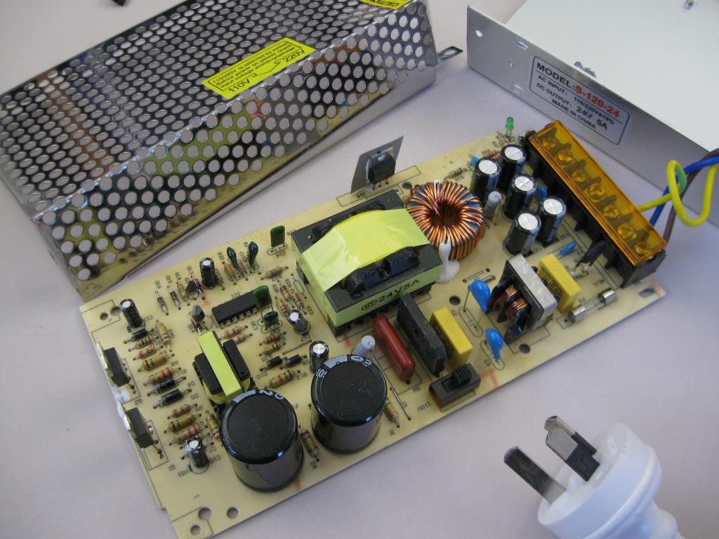
It includes a rectifier and an L-filter. The key to the success of the computer's power supply circuit is a secondary power transformer with 5- and 12-volt windings. In high-power models (250 W and more), 2 parallel 5-V windings are used, providing a higher output current, which are considered as one.
Each winding in the center is grounded to provide full wave rectification using only 2 diodes (usually 4 are required). The direction of the rectifiers determines the polarity of the output voltage of the power supply. Common cathodes are positive, and anodes are negative.
Due to the high current requirements, the +5 V rectifier is usually an array of parallel Schottky diodes, which is mounted on a radiator. The -5 V output is often output from the -12 V rectifier through a regulator, and not from the 5-V transformer winding. But both are possible.
User reviews recommend checking the fan of the computer's power supply, as insufficient cooling can lead to failure of various elements, especially a pulse transformer and Schottky diodes. In any case, you should lubricate it by removing the sticker and opening the rubber cover that covers the bearing, or replace it with a new one.
The output of the rectifiers is first filtered by a choke, and then a powerful capacitor. In some designs, the 5-volt line is filtered twice to reduce ripple by cascading two L-filters. There is always a resistor that serves to discharge the capacitors after turning off the power.
The most common cause of malfunctions of the low-voltage part of the PSU circuit is called a short-circuited rectifier. If one diode burns out, then the same thing happens with its pair, so you need to change them at the same time. The next problem is a short-circuited capacitor, which usually gives not so much damage. In most cases, its failure is limited to only one output line, but not always.
Troubleshooting parts
This operation requires access to the underside of the circuit board. According to user reviews, this is the most difficult part of the repair, since there are no two identical PSUs. Use your imagination and exercise caution so as not to damage other components in the process. For example, dismantling and repeated rotation of the board can lead to breakage of the wires attached to it.
Now difficulties begin, because you need to find damaged parts. An ohmmeter is a good way of sensing suspicious areas for the presence of short-circuited sections. After detection, it is necessary to work with a soldering iron, because it is almost impossible to determine a shorted diode and capacitor without removing one or the other. Since the rectifier is the most likely culprit and it is easier to dismantle it (the capacitors are glued to the board), it is better to start with it.
5- and 12-volt diodes are most likely located inside parts mounted on the radiator. The larger one is a +5 V rectifier, and a smaller one is +12 V. Rectifiers of negative voltage can be made with separate diodes.
Having removed the suspicious rectifier, it is necessary to repeat the resistance test of the faulty voltage output line. If it is within the normal range, then you need to discard the defective part and replace it with a new one (if the price of the power supply for the computer is higher than the cost of repairing it). New diodes are best soldered to the back of the circuit board. Such alteration of the computer power supply unit greatly simplifies the work. If the output is still short, replace the capacitor and check again. Did not help? Make sure that the replacement is carried out correctly.
Original spare parts always cost more than their counterparts, so user reviews recommend using the latter.
When the line has a three-pin voltage regulator, it is necessary to check the resistance between its input and output to ground. If only the output is shorted, the output capacitor is out of order, if only the input, the rectifiers are faulty. When both are shorted, there is a likelihood that both the diodes and the voltage regulator are faulty. To test this theory, the regulator needs to be removed and resistance measured again. If everything is in order, then it is necessary to replace it.
Repair of the high voltage part
If a fuse blows when it is turned on, then this, according to user reviews, indicates a problem in the high-voltage part of the computer’s power supply circuit. This follows from the fact that the low-voltage part has an automatic shutdown circuit, which responds much faster than a fuse. A low voltage problem shuts off the power long before the fuse blows. This does not necessarily mean that the low-voltage part is in order, as a failure of the -12 V line can lead to cascade damage that leads to the high-voltage section.
The latter is divided into 2 parts: a high-voltage power supply and a switching circuit. In the latter, most failures occur.
According to reviews, if the fuse has a "mirror" appearance, then you can be sure that at least one of the two switching transistors is shorted. As a rule, they fail in pairs. These transistors are installed on the radiator of about 2 of the largest capacitors. Having installed the red probe of the multimeter on the collector of the first transistor, it is necessary to check the resistance between it and the emitter, and then between the collector and the base. If a short circuit is found, then you need to replace the transistor and the damper diode, which connects the emitter to the collector.
Also, reviews recommend changing the low-resistance resistor, which is connected in series with the base of the transistor. It is often used as a fuse, which fails when the switch malfunctions. Its purpose is to protect other components of the circuit. If the resistor is burnt beyond recognition, it can be replaced by any resistance with a power of 0.25 W with a value from 1 to 10 Ohms. However, sometimes even a fusible resistor is not fast enough to prevent damage. Therefore, before installing new parts, it is advisable to check the pulse formation circuit (as a rule, which is a combination of a resistor, diode, and capacitor) associated with the base. A quick way to test all 3 components at once is to treat them as a separate diode, checking it as a whole for a short and open. Next, you need to repeat the procedure for the second switching transistor.
The high-voltage power supply is designed as a simple voltage doubler with an output of about 300 V. Although this part rarely fails by itself, a short-circuited transistor can damage the bridge rectifier in an instant. It is necessary to check the AC input for short circuits and replace the entire bridge if it is found. Bridges can be made either by separate diodes, or by a large rectangular module. It is likely that there will be a 1-ohm resistor in the circuit, the resistance of which also needs to be measured. You should also check if one of the two capacitors is shorted.
When powered from 220 V, capacitors serve as voltage dividers to provide artificial grounding. , 220 . . . , . . , , , , Panasonic TSU.
At this point, the computer's power supply should already be working. But before connecting it, reviews advise once again to make sure that everything necessary is done. Namely:
- A final check of the resistances on the output lines has been completed, and all of them comply with the specifications.
- Measured the resistance at the AC input (when the power is on), and it is not less than 1 MΩ.
- Fuse tested.
- There are no dangling wires or burnt parts.
Fine! Further, users are advised to install the power supply in the computer, connect the dummy load to one of the drive connectors and turn on the PC. If both lights turn on, the device is repaired. The power supply works because it requires -5 and -12 V lines to operate. Therefore, they do not need to be checked.
last try
According to user reviews, in 9 cases out of 10, the troubleshooting methods presented in this article will help solve PC power problems. But what if the PSU still does not work? There can be many reasons, from a faulty transformer to poor soldering.
But if the intention to restore the system’s performance is great, and the price of the power supply for the computer is much higher than the cost of its repair, then you should familiarize yourself with the pulse width modulator. It controls the key transistors, and when it does not work, then everything else does not work. This is usually one integrated chip. But before replacing it, it is necessary to check its performance. To do this, you need an oscilloscope and a power source.
According to reviews, the easiest way to test a PWM chip is to take a drive connector and feed +12 V into the yellow wire from an independent DC source. This can be done using another PSU or any other DC source (including battery). After that, you should check the output signals on pins 8 and 11. Both outputs should be active square waves. If this cannot be done, then it is necessary to ground pin 4 and try again. Does the oscilloscope show anything again? Need to replace the chip. If waves are visible, then the comparator is the most likely culprit. It is inexpensive, readily available, so it’s worth a try. If the PSU does not work after that, then the owners recommend replacing it with another one or using the motherboard in another system.