The world has been engaged in a process approach to organizing business for a long time and quite effectively, and the Business Process Model and Notation (BPMN, notation) standard is a well-thought-out procedure with the correct description of business processes. Companies are constantly improving various specializations of this standard and thereby achieve a very significant increase in all the quality indicators of their work. BPMN notation is understandable not only for experts in the subject area in which it was created, any employee can operate with its logical calculations.
Modeling and standardization
Along with simplicity, this standardization is the most comprehensive model of the described business process, written in machine-readable form. BPMN (if you look at it in the BPMN 2.0 notation version) builds models of the most complex processes in business very powerfully and expressively, and in the most understandable system. Most importantly, along with this standard, graphic models are defined and converted into a well-structured and machine-readable form that is based on XML. The language of BPMN notation is absolutely executable, that is, it allows you to simulate processes that are subsequently performed using BPMS (automated business process management systems). Such standardization is extremely useful precisely because model developers can use some software products, and artists - others if they support this standard.
To build a particular model, more than one version can be used (BPMN 2.0 notation (PDF) and others), sometimes the model is composed of fragments of different notations, but the method of systematizing and reading them is the same. A growing number of entrepreneurs are introducing business processes based on this standard in their companies. The demand for specialists who know this modeling language is growing every day. A growing number of people are studying the graphic elements of BPMN notation and the rules for building models. To do this, there are special courses where people wishing to get acquainted with the purpose of this language, with the types of diagrams, see the possibilities of automatic execution of the constructed models. The most interesting thing is practical experience in BPMN 2.0 notation (in Russian, too), modeling and analysis, development of a business process.
Specialists
Who is capable of describing business processes? BPMN-notation modeling is easily performed by all those involved in automation, the development of business processes. These are business consultants, business analysts, project managers, system analysts, architects and computer system developers, methodologists, and quality service workers. Typically, these people are able to read technical documentation in English, participated in any analysis projects, as described by BPMN notations, optimized or automated business projects, or developed and maintained software. This methodology has an international status, and not a corporate one, like many other standards, and not even national. That is why, since 2005, they have been analyzing and reorganizing the business with the help of process modeling in BPMN notation.
This technique provided accessible information to almost all users - from the largest analysts who create the schemes, and developers who implement technologies for performing business processes according to these schemes, to company leaders, that is, ordinary users who are busy managing and monitoring the implementation of the constructed model. In this way, Business Process Modeling (BPMN) notations bridge the gap between model creation and implementation. Here are the best ideas available in other methodologies. For example, for better flexibility and readability , business process modeling in BPMN 2.0 notation is carried out in the tradition of flowcharts.
Symbols (Elements) BPMN
Supported and developed by BPMN, OMG. This is not a meme of Internet regulars that means “about mine got,” but rather the very famous company Object Management Group, in which more than eight hundred companies are developing standards that are similar to BPMN notations. All the useful changes in the new versions we owe to the OMG developers. It was this organization that chose the promotion of UML BPMN notation as a key direction, with which object-oriented systems are modeled. Therefore, when developing diagrams, in addition to concepts and concepts (control flow, action, data object, etc.), BPMN has many concepts that are characteristic of an object-oriented approach: message, exchange, and message flow.
Symbols of graphic notation are sorted by purpose and are combined into categories. These are: Flow Objects - flow objects, Data - data, Swimlanes - areas of responsibility, Connecting Objects - connecting objects, Artifacts - artifacts. The control flow, the data object and the symbols of the flow objects are further divided into subgroups according to the semantic criterion in order to display the specifics of the events that occur, flow branching features, actions and so on. Specify the specifics due to additional graphic images - markers, icons placed inside the main symbol. Also, event symbols come in a different outline and background color.
Time Events
During the execution of a business process, the most diverse and numerous events always occur that exert their influence, despite the fact that they are most often optional elements and are not displayed in the business process diagram. This is receiving and responding to a message, changing the status in documents and much more that there is no point in listing - a lot of events happen literally at every step. To classify them, the attributes of each are determined. The first group - by the time of the onset. This is the starting event that will show the start of the chart. From here, the control flow can only be outgoing, and the message flow can go in both directions. The start event in a business process diagram is usually one, but you may not display it at all. Sometimes there are even several of them, if the mapping occurs with tracks, pools, and expanded subprocesses. The contour of the event is represented by a thin single line.
The final event is the result of the business process. The control flow only enters here, and the message flow still moves to the input and output. The incoming stream is shown by an arrow. The diagram displays only one final event or several - they are circled in the form of a bold single line. An intermediate event is any of the others that occur during the execution of a business process. One stream enters here and one exits too. Only the Boundary (boundary event) arises and is processed immediately - either at the very beginning or at the end of the action. It is displayed on the contour (boundary) of the action, and contains only one stream - either incoming or outgoing. And such an event is indicated by a thin double line.
Events: Subprocess Interruption and Result Type
Since the events during the modeling of a business process occur very differently, the next block classified those that can interrupt an action. The non-stop events are the first to be marked - this is an intermediate or start event that occurs during execution, but initiates the outgoing flow associated with it only when the action is completed. The contour of such an event is depicted by a dashed line. Next is an interrupt event that occurs before or after a standard action. In exceptional situations, this event requires a stop or termination if the necessary information is missing or an error is displayed during processing, if additional actions and the like appear. Here the outline is shown by a solid line.
The third type of event is classified according to the type of result. First of all, here we need to talk about the initiator of processing. This is an intermediate or starting event that occurs as a result of actions and is the result of the process - standard or not. The initiating event is shown by an open icon. It is necessary to add another event to this section, which also speaks of effectiveness, only here it is the result of processing. This is an intermediate or final event that occurs during the execution of actions and is one of the final results of the process - standard or not, it is indicated by a filled icon.
Actions
The process depicted in the form of a diagram looks like an ordered set of actions that are performed to obtain a specific result. In the vertical BPMN notation diagram, a sequence is shown from top to bottom that shows the progress of the process in time. You can also trace it in the direction of the arrows of the connecting elements from left to right. The displayed actions have three main types and many varieties, each of which has its own icon or icon.
Task - a task. Elementary action, that is, indivisible. The variety or specificity of the task is displayed by a marker or icon in the upper left corner of the action symbol. The task can be Service, to provide a service that is an automated application or web service. Send - send a message. If at least once a message is sent, the task can be considered completed. Receive - receiving a message (the same principle: if a message is received once, the task is completed). The task of the User - the user, is considered characteristic, is performed by the contractor using software and the assistance of other employees. A task requiring manual execution is Manual, which is executed without the aid of automation. Business-Rule - a business rule, according to the technology, the implementation of this task depends on the circumstances, the task of the business rule helps to choose a method. Script - a script where the execution of operations is strictly in the order described in a language recognized by the executor. Usually this type of task is performed automatically.
Subprocesses
Sub-Process is a subprocess. It includes gateways in BPMN notation, workflows, events, and many other actions. Thus, the subprocess is a composite action, parts of which are directly displayed inside the symbol on the diagram or are placed on a separate decomposition diagram. In the latter case, the + sign should be displayed on the main diagram in the center of the subprocess (lower edge of the action). There are standard subprocesses, but they are not enough, therefore, two of its specific varieties appeared. This is an Event Sub-Process - an event subprocess that always starts when a start event occurs. The diagram shows it in no way connected with other actions and workflows. The contour of such a subprocess is depicted by dots.
The second type is Transaction, which is an action consisting of different operations with a successful completion, that is, obtaining a positive result. A specific result can only be obtained if all components are successfully completed. If problems arise during the execution of the subprocess, the results of all previous operations will be canceled (event cancellation). Such interference may be the inability to perform a particular operation or its incorrect execution. In order not to cancel previous events, you can try to compensate for the failed operation (event compensation). The contour of such a subprocess is shown by a double solid line. To include all tasks or subprocesses reused in the diagram, there is a Call - a call, which is indicated by a bold outline in the diagram.
Gateways
Gateways in BPMN notation are intended to indicate the specifics of the workflow and their passage through parallel or alternative branches. The gateway can do without outgoing or incoming flows, but always has at least two of its own either incoming flows or outgoing flows. The token inside its symbol defines the type of gateway. It can be Exclusive, XOR - exclusive with an exclusive "or", designed to split the stream into alternative routes. During the process, only one of the proposed routes can be activated. Skipping conditions are located next to the designation line. Inclusive, OR - non-exclusive with a logical "or" gateway, designed to divide the stream into routes, where each is activated if the condition for the truth of the logical expression associated with it is met. In this process, you can perform several routes, but if at least one is missing truth, then the choice is impossible.
An analogue of a non-exclusive gateway is Complex (complex). The difference is that the expression that determines the activation of a particular workflow is only one. Parallel, AND - a parallel gateway with the logical "and" is needed to branch or merge parallel operations. Exclusive Event-Based - an exclusive, but event-based gateway that divides the workflow into alternative routes. Exclusive Event-Based Gateway to start a Process is also an exclusive gateway, the events on which it is based start the entire process. This is the initial symbol of a process or subprocess; it does not have incoming flows. Parallel Event-Based Gateway to start a Process works in the same way - a parallel gateway, also based on events that trigger the process. However, with its help it is possible to activate several processes at the same time if the events associated with them work. Naturally, it does not have incoming flows. In the pictures, the BPMN notation is clearly visible in the diagramming examples with two types of gateways.
Data and Streams
The data object is specifically contained and used in diagrams, which demonstrates the use of additional markers. Data Inputs - input data, that is, the source information in order to begin the execution of actions. Depicted at the top of the symbol. Data Collection - a data set, that is, an entire array or collection of data of the same type. Displayed below the symbol. A data object and actions are combined by association.
The standard image of the workflow can be supplemented in the diagram by indicating specific flows. Conditional Sequence Flow - designation of a conditional workflow when branching it. It is displayed proceeding from action (if there is no desire to use the gateway in the diagram). Default Sequence Flow — the default workflow most often comes from a gateway or action, and is not associated with logical expressions.
Examples and conclusions
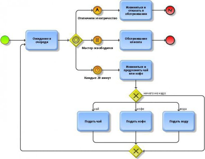
The starting event, as the name suggests, points to the starting point of a process. This is the starting point, which means the absence of any kind of incoming stream. The starting event in the BPMN notation examples is indicated by a circle in which the center is free. Such an event may be a letter or a call from a client, for example, sent to an online store or to the website of a company that models this business process. Further, the workflow goes along the lines and indicates the execution of the process up to the red circle, which indicates completion, the final event. By the way, there may be several of them, and it is easy to trace exactly where the workflow came to an end, completing the process. No outgoing flow from the red circle is possible.
If the diagram is not drawn in color, then the final event is highlighted in bold in a circle shape. For example, in practice, this event may be the delivery of the ordered goods, which went all the way from clearance through processing to delivery. In the course of all this work, the diagram shows the actions that were performed on the way from the start to the end event. The action is indicated by a rounded rectangle. Gateways - diamonds. This language is understandable to users, it is only a little familiar with the display system, which is present here in the illustrations.