How is the distribution of electricity and its transmission from the main power source to the consumer? This issue is quite complicated, since the source is a substation, which can be located at a considerable distance from the city, but at the same time energy must be delivered with maximum efficiency. This issue should be considered in more detail.
General process description
As mentioned earlier, the initial facility from which the distribution of electricity begins is today the power plant. Nowadays, there are three main types of stations that can supply consumers with electricity. This can be a thermal power station (TPP), a hydroelectric power station (HPP) and a nuclear power station (NPP). In addition to these basic types, there are also solar or wind stations, however they are used for more local purposes.
These three types of station are both the source and the first point of distribution of electricity. In order to carry out a process such as the transmission of electrical energy, it is necessary to significantly increase the voltage. The farther the consumer is, the higher the voltage should be. So, the increase can reach up to 1150 kV. An increase in voltage is necessary in order to reduce the current strength. In this case, the resistance in the wires also drops. This effect allows you to transfer current with the least power loss. In order to increase the voltage to the desired value, each station has a step-up transformer. After the passage of the section with the transformer, the electric current is transmitted via power lines to the central distribution board. CRP is a central distribution station where direct electricity distribution is carried out.
General description of the current path
Objects such as the central heating circuit are already in close proximity to cities, villages, etc. Here, not only distribution, but also a decrease in voltage to 220 or 110 kV occurs. After that, electricity is transferred to substations already located in the city.
When passing through such small substations, the voltage decreases once again, but already to 6-10 kV. After that, the transmission and distribution of electricity is carried out at transformer points located in different sections of the city. It is also worth noting here that the transfer of energy within the city to TP is no longer carried out with the help of power lines, but with the help of laid underground cables. This is much more appropriate than the use of power lines. A transformer station is the last facility at which electricity is distributed and transmitted, as well as its last reduction. In such areas, the voltage decreases to the usual 0.4 kV, i.e. 380 V. Then it is transferred to private, multi-storey buildings, garage cooperatives, etc.
If we briefly consider the transmission path, it is approximately as follows: an energy source (10 kV power plant) - a step-up transformer to 110-1150 kV - power transmission line - a substation with a step-down transformer - a transformer station with a voltage reduction of 10-0.4 kV - consumers (private sector, residential buildings, etc.).
Process features
The production and distribution of electricity, as well as the process of its transmission has an important feature - all these processes are continuous. In other words, the production of electric energy coincides in time with the process of its consumption, which is why electric stations, networks and receivers are interconnected by such a concept as the commonality of the regime. This property necessitates the organization of energy systems in order to more effectively deal with the production and distribution of electricity.
It is very important to understand what such an energy system is. This is a set of all stations, power lines, substations and other heating networks, which are interconnected by such a property as the commonality of the regime, as well as by a single process for the production of electric energy. In addition, the processes of transformation and distribution in these areas are carried out under the overall control of this entire system.
The main working unit in such systems is the electrical installation. This equipment is intended for the production, conversion, transmission and distribution of electricity. The receipt of this energy is carried out by electrical receivers. As for the plants themselves, depending on the operating voltage, they are divided into two classes. The first category works with voltages up to 1000 V, and the second, on the contrary, with voltages from 1000 V and higher.
In addition, there are also special devices for receiving, transmitting and distributing electricity - a switchgear (RU). This is an electrical installation, which consists of such structural elements as prefabricated and connecting buses, devices for switching and protection, automation, telemechanics, measuring instruments and auxiliary devices. These units are also divided into two categories. The first is open devices that can be operated outdoors, and closed, used only when located inside the building. As for the operation of such devices within the city, in most cases it is the second option that is used.
One of the last lines of the system of transmission and distribution of electricity is a substation. This is an object that consists of switchgear up to 1000 V and from 1000 V, as well as power transformers and other auxiliary units.
Consideration of the energy distribution scheme
In order to consider in more detail the process of production, transmission and distribution of electricity, we can take as an example the structural diagram of the supply of electric energy to the city.
In this case, the process begins with the fact that the generators at the state district power station (state regional power station) generate a voltage of 6, 10 or 20 kV. In the presence of such voltage, transmitting it to a distance of more than 4-6 km is not economical, as there will be large losses. In order to significantly reduce power loss, a power transformer is included in the transmission line, which is designed to increase the voltage to values such as 35, 110, 150, 220, 330, 500, 750 kV. The value is selected depending on how far the consumer is. After this follows the point of lowering electric energy, which is presented in the form of a step-down substation located in the city. The voltage decreases to 6-10 kV. It is worth adding here that such a substation consists of two parts. The first part of the open type is designed for a voltage of 110-220 kV. The second part is closed, it includes a power distribution device (RU), designed for a voltage of 6-10 kV.
Electricity supply sections
In addition to the devices that were listed earlier, the energy supply system also includes objects such as a power cable line - PKL, a distribution cable line - RKL, a cable line with a voltage of 0.4 kV - KL, an input type switchgear in a residential building - ASU, the main step-down substation at the plant - GPP, power distribution cabinet or switchboard switchgear, located in the factory’s workshop, and designed for 0.4 kV.
Also, in the circuit, there may be such a section as a power center - CPU. It is important to note here that this object can be represented in mind of two different devices. This may be a secondary voltage switchgear in a step-down substation. In addition, it will also include a device that will perform the functions of voltage regulation and its subsequent delivery to consumers. The second embodiment is a transformer for transmitting and distributing electricity, or a generator voltage switchgear directly at the power plant.
It should be noted that the CPU is always connected to the distribution point of the RP. The line that connects these two objects has no distribution of electrical energy along its entire length. Such lines are commonly called cable lines.
To date, equipment such as KTP - a complete transformer substation can be used in the grid. It consists of several transformers, a distribution or input device, designed for operation with a voltage of 6-10 kV. A 0.4 kV switchgear is also included. All these devices are interconnected by current conductors, and the kit is delivered ready-made or ready-for-assembly. Reception and distribution of electricity can also occur on high structures or on the supports of power lines. Such structures are called either pole or mast transformer substations (MTP).
The first category of electrical receivers
Today, there are three categories of power consumers, which differ in the degree of reliability.
The first category of electrical receivers includes those objects, in the event of a power failure which causes serious enough problems. The latter include the following: a threat to human life, severe damage to the national economy, damage to expensive equipment from the main group, mass rejects of products, the destruction of an established technological process for generating and distributing electricity, and possible disruption of important elements of the public utilities. Such electrical appliances include buildings with a large crowd of people, for example, a theater, supermarkets, a department store, etc. Also, electrified vehicles (metro, trolleybus, tram) also belong to this group.
As for the supply of electricity to these facilities, they should be provided with electricity from two sources that are independent of each other. Disconnection from the network of such buildings is allowed only for the period during which the backup power source will be launched. In other words, the power distribution system should provide for a quick transition from one source to another in case of emergency. In this case, an independent power source is considered to be the one at which the voltage will remain even if it disappears on other sources that supply the same power receiver.
The first category also includes devices that must be powered immediately from three independent sources. This is a special group whose work must be ensured in an uninterrupted mode. That is, it is not allowed to disconnect from the power supply even while the emergency source is on. Most often, such a group includes receivers, the failure of which entails the emergence of a threat to human life (explosion, fire, etc.).
The second and third category of receivers
Electricity distribution systems with the connection of the second category of electrical receivers include such equipment, when the power is turned off, there will be a massive downtime of working mechanisms and industrial transport, lack of products, as well as disruptions to the mass number of people living both within the city and beyond the limits. Such a group of electrical receivers includes residential buildings above 4 floors, schools and hospitals, power plants whose power off will not result in the failure of expensive equipment, as well as other groups of electrical consumers with a total load of 400 to 10,000 kV.
As sources of energy in this category should be two independent stations. In addition, disconnection from the main power source of these facilities is allowed until the on-duty personnel put the backup source into operation, or the on-duty team of workers at the nearest power supply station does this.
As for the third category of receivers, then all the remaining devices that can be powered by just 1 power source belong to them. In addition, disconnection from the network of such receivers is allowed for the period of repair or replacement of damaged equipment for a period of not more than a day.
Schematic diagram of the supply and distribution of electrical energy
Monitoring the distribution of electricity and its transmission from a source to a receiver of the third category within the city is easiest to implement using a radial deadlock scheme. However, such a circuit has one significant drawback, which is that if any one element of the system fails, all the receivers connected to such a circuit will remain without electricity. This will continue until the damaged part of the circuit is replaced. Due to this drawback, it is not recommended to use such a switching circuit.
If we talk about the connection and distribution of energy for receivers of the second and third categories, then here you can use the ring circuit diagram. With this connection, if one of the power lines fails, you can restore power to all receivers connected to such a network in manual mode if you disconnect power from the main source and start the backup. The ring circuit differs from the radial one in that it has special sections where disconnectors or switches are in disconnected mode. If the main power supply is damaged, they can be turned on to restore the supply, but from the backup line. It will also serve as a good advantage if any repair work is necessary on the main line. A break in the power supply of such a line is allowed for a period of about two hours. This time is enough to disconnect the damaged main power source and connect the backup to the network so that it distributes electricity.
There is an even more reliable way to connect and distribute energy - this is a circuit with the parallel connection of two supply lines or the introduction of automatic connection of a backup source. In the presence of such a circuit, the damaged line will be disconnected from the general distribution system using two switches located at each end of the line. The supply of electricity in this case will be carried out in a still uninterrupted mode, but already along the second line. Such a scheme is relevant for receivers of the second category.
Distribution schemes for the first category of receivers
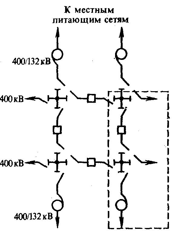
As for the distribution of energy to power the receivers of the first category, in this case it is necessary to connect from two independent power centers at the same time. In addition, in such schemes often not one distribution point is used, but two, and a system for automatically switching on the backup power is always provided.
For electrical receivers that belong to the first category, the automatic switching to backup power is installed on the input-distribution devices. With such a connection system, the distribution of electric current is carried out using two power lines, each of which is characterized by a voltage of up to 1 kV, and are also connected to independent transformers.
Other receiver distribution and power schemes
In order to distribute electricity as efficiently as possible among the receivers of the second category, you can use a circuit with maximum current protection of one or two switchgears, as well as a circuit with automatic backup power. However, there is a certain requirement. You can use these schemes only if the costs of material resources for their arrangement do not grow by more than 5%, compared with the arrangement of manual transition to a backup power source. In addition, it is necessary to equip such sections in such a way that one line can take on the load from the second, taking into account the short-term overload. This is necessary, since if one of them fails, the distribution of the entire voltage will go over to the remaining one.
There is a fairly common ray connection and distribution scheme. In this case, one distribution point will be powered by two different transformers. , 1000 . , , , - .
, , , . , . , . .
, , , – .