DKVR-20-13 is a vertical-tube-type steam boiler that has a shielded combustion chamber. Its design also includes a boiling beam. These structural elements are carried out according to the scheme "D". A distinctive feature of this scheme is the lateral arrangement of the convective part of the device with respect to its combustion chamber.
The main indicators of the unit
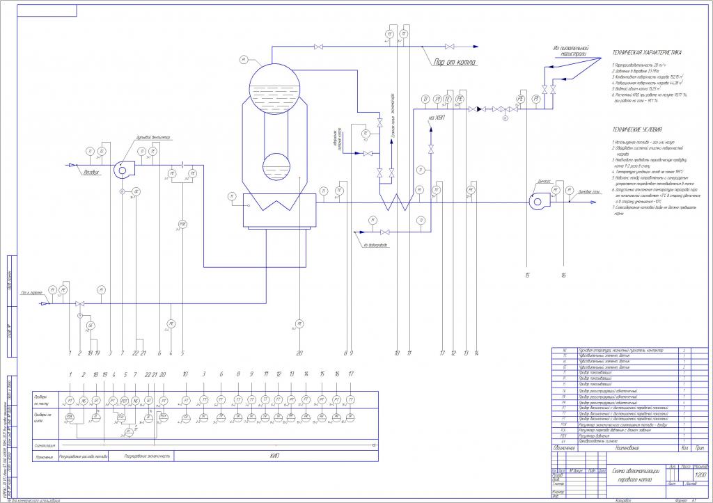
It is worth starting with the technical characteristics of DKVR-20-13. As already noted earlier, this type of unit belongs to steam boilers. Its steam capacity is 20 t / h. As for the type of fuel used for work, it is gas or liquid fuel. Excessive or working pressure of the coolant at the outlet of the boiler is 1.3 MPa. The steam temperature at the outlet is considered one of the main indicators. It can be equal to 194 degrees Celsius in the case of saturated steam or 250 degrees in the case of superheated. An important component is the temperature of the feed water - 100 degrees. The coefficient of performance, according to calculations, is 92%. The fuel consumption is determined in kg / h and amounts to 1470. The boiler belongs to large-sized installations, and its weight is 44634 kg.
Unit Description
The steam boiler DKVR-20-13 consists of several basic structural elements: the upper short drum and the lower, shielded combustion chamber, which was mentioned earlier. Next, it is worthwhile to consider this unit and its parts in more detail.
The device DKVR-20-13 has a feature that the combustion chamber is divided into two parts: the furnace itself, as well as the afterburner. This chamber is separated from the furnace by the rear screen of the boiler. Hot gases are supplied to the boiler pipes by direct current and over the entire width of the beam. On the way, they do not have any partitions. However, in the case of additional installation of a superheater on the boiler DKVR-20-13, some of these pipes may not be installed. The superheater itself will consist of a couple of packages. They will be located on opposite sides of the boiler. After working out, superheated steam from both packages will be diverted to a special collector. The device of the DKVR-20-13 aggregate uses feed water, which will be supplied to the upper drum. Now about him.
Boiler drum
The upper drum is subjected to severe overheating, and therefore it must be cooled. To cool the walls of this structural element, a mixture of water and steam is used, which emerges from the pipes of both the side screens and the front of the convection beam.
The upper drum has an element called the upper generatrix. It usually contains structural elements such as safety valves, a steam valve or a gate valve, a valve for the possible selection of steam for your own needs (for blowing).
In the upper drum there is a water space through which the feed pipe passes. In the space filled with steam pass separation devices.
Distinctive features
When describing the DKVR-20-13, it should be noted that there are certain distinctive features in the design. Which distinguish this model from others, with a lower rate of steam production. Among them it is worth noting:
- The upper drum of the unit 20-13 is shorter, because of which it does not fall within the boiler furnace. At the same time, both the upper and lower drums are equal in length - 4500 mm. It is also worth adding that the presence of a shortened upper drum led to the absence of the need for gunning, and also increased the reliability of the equipment as a whole.
- Due to the fact that the upper drum was reduced, and the amount of water and steam produced was required to remain at the same level, it was decided to add two external cyclones to the design. These elements produce about 20% of the total steam.
- The lower drum has also undergone minor changes. It was raised above the zero mark, which made it possible to increase accessibility and convenience during inspection and maintenance.
- The boiler DKVR-20-13 has a large number of screens. Two of them are located on the right side, two more on the left side, one front and one rear screen. In addition, each of them has two collectors in its composition. Thus, it turns out that the boiler is equipped with 12 collectors, six of which are located in the upper part, six in the lower.
- Another design feature affecting the side screens is their subdivision into two blocks. The first block is considered to be the side screens for the first stage of evaporation, respectively, the second block is the second stage of evaporation. In addition, the second block is usually located in front of the convective beam, and the screens are usually counted from the front of the boiler.
- The last design feature is the execution of side pipes for screens with an L-shaped form. Their installation is carried out according to the following principles. For example, the first pipe for the right side screen will be welded with its lower end to the lower right collector, and its upper end is welded to the upper collector of the left screen. The first pipe for the left screen will be mounted on the same principle. Further cross-connection thus leads to the fact that the combustion chamber is completely shielded.
And in the end, we can add that the convective beam does not have partitions in its design.
Common assembly problems
Repair of boilers should be trusted only to professionals. Among the most common problems that can be detected, scale formation is highlighted. This defect will be characterized by a decrease in the heat output of the boiler, as well as a decrease in its overall performance indicator. Among other common causes of breakdowns, improper maintenance or non-compliance with the rule of these works is highlighted. Often the cause may be an error at the stage of system design or installation of the unit itself.
In any case, repairing a boiler of this type is very expensive. To avoid the need for this work, it is necessary to carry out diagnostics of all parts and the system as a whole as often as possible. In addition, preventive cleaning operations should be carried out to avoid the formation of scale.
Lining. Features
During the installation of the boiler DKVR-20-13, the lining is an essential part. At the same time, the wall thickness for it should be 510 mm - this is the thickness of two bricks. All walls should be of this thickness except for the back. Here, a reduction to a thickness of 1.5 bricks or 380 mm is allowed. In addition, the back wall is usually coated on the outside with a 20 mm thick plaster layer. This is done in order to reduce the number of suction cups.
This lining is considered heavy, and therefore it is made of red brick. It also uses fireclay bricks, which lay the walls facing the firebox. Their thickness should be 125 mm.
The walls of the afterburner should be 250 mm thick. Between the tubes of the beam it is necessary to make a partition. Both of these structural elements of the lining should be made of fireclay brick.
Front screen operation
The operating manual for the boiler DKVR-20-13 is attached to each unit and contains all the necessary instructions for the use of the unit, its care and maintenance. However, the work of some parts should be read in more detail.
In the front screen there is a circulation of water along the circuit. The lower collector of this screen belongs to the first stage of evaporation. It is fed with water from the upper drum through two bypass pipes. During operation of the unit, not all water evaporates. Unevaporated liquid will also enter this collector from the upper drum. There are four special downpipes for this. Further, there are lifting pipes in the structure along which the liquid will move upward from the lower manifold. It will heat up, turning into a steam-water mixture, after which it will be supplied to the upper collector.
Gas movement
After fuel combustion, gases will form which move into the afterburner. A superheater is usually installed at the end of such a chamber. Since the design of this particular boiler does not provide for the presence of partitions in front of the beam, these exhaust gases will pass through it, giving off their heat. After that, they will be discharged from the boiler along its entire width of the back wall. After that, there is a special gas duct through which gases will be delivered to the economizer.
Design changes
As noted earlier, data began to be produced since 1961. The peculiarity was that they were originally intended to burn solid fuels, such as coal and brown coal or anthracite. However, after that, the fuel balance was changed in the country and it was necessary to switch to burning liquid and gas fuels. This did not make any significant changes to the design.
It is important to note here that after switching to such fuels, a forced operation mode from nominal to 140% was allowed. This has led to a significant increase in emergency situations. Their bulk was the failure of the salt compartment and cyclones.
Hot water mode
In the end, it is worth adding that the boiler can be operated in hot water mode. This allows you to reduce fuel consumption during operation, increase plant productivity, reduce the cost of resources for the unit’s own needs, and reduce the cost of preparing the liquid.
If we consider all these advantages in aggregate from the point of view of increasing efficiency, then on average this indicator increases by 2-2.5%.
Based on the foregoing, we can draw the following conclusion. These units were good units for their time, but now technology allows us to manufacture and operate better equipment.